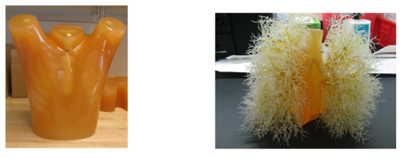
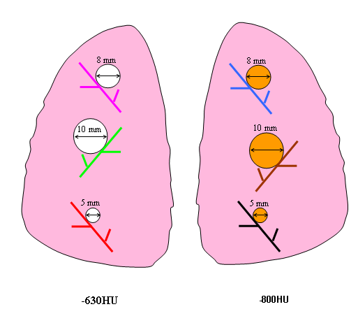
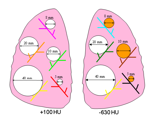
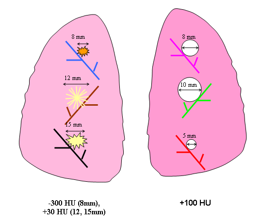
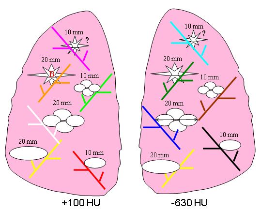
NBIA DICOM Radiology Portal in terms of nodule positioning, size, shape, and density. Figures 3-6 show a schematic diagram of the currently available layouts. All tables and figures in this document will be updated as more data is posted. 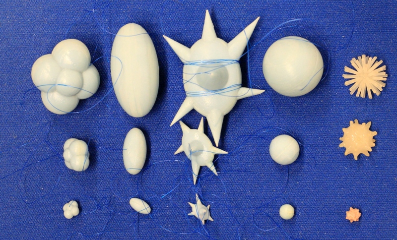 Image Modified Image Modified Figure 2: Photographs of the different types of synthetic nodules used in this study. Each column shows example nodules in three sizes, with lobulated, elliptical, spiculated, spherical, and irregular nodules shown from left to right. The three sizes shown here were manufactured to have the equivalent volumes of spherical nodules with diameters of 5, 10, and 20 mm (with the exception of the irregular shapes which have nominal diameters of about 5, 10, 12 mm). Additional nodules used in this study span the size range between 5-60mm. Nodule layout | Vessel attachment | Nodule placement and description | Left lung | Right lung | Nominal diameter (mm) | Shape* | HU | Nominal diameter (mm) | Shape | HU | 1 | attached | 5,8,10 | SPH | -800 | 5,8,10 | SPH | -630 | 2 | attached | 5,8,10 | SPH | 100 | 8,12,15 | irregular | -300, 30,30 | 3 | attached | 5,8,10,20,40 | SPH | 100 | 5,8,10,20,40 | SPH | -630 | 4 | attached | 10, 20, 10, 20, 10, 20 | ELL, ELL, LOB, LOB, SPI, SPI | -630 | 10, 20, 10, 20, 10, 20 | ELL^, ELL, LOB, LOB, SPI, SPI | 100 |
Table 1. Summary of currently available nodule layouts. *SPH- spherical, ELL- elliptical, LOB- lobulated, SPI- spiculated. ^Note: The 10mm, 100HU elliptical nodule in the right lung has a large hole in it. A replacement was scanned as part of Nodule 6 which will be released by the end of 2014. The phantom was scanned using a Philips 16-row scanner (Mx8000 IDT, Philips Healthcare, Andover, MA) and a Siemens 64-row scanner (Somatom Definition 64, Siemens Medical Solutions USA, Inc., Malvern, PA). Scans were acquired with varying combinations of effective dose, pitch, and slice collimation, and were reconstructed with varying combinations of slice thicknesses and reconstruction kernels. Ten exposures were acquired for each imaging protocol. The phantom position was not changed during the 10 repeat exposures; however it was repositioned between different imaging protocols or different nodule layouts. Table 2 summarizes the imaging protocols for the nodule layout. NOTE: Each study in the database contains 10 repeat scans for that particular acquisition protocol, multiplied by the number of reconstructions. The study and series descriptions contain the following information: Study description: Contains information on: the scanner vendor (currently Philips or Siemens), the exposure (in mAs), the pitch (currently either 1.2 or 0.9 according to the definition , where Δd is the patient table travel in the horizontal direction and T is the detector width at the isocenter plane), and slice collimation (in mm). Series description: Contains information on reconstructed slice thickness (in mm), reconstructed slice increment (in mm), and reconstruction filter or kernel (currently either C for detail, or B for medium). |